Release - Move 1200 L

-
Stelos 800 L
Stelos: Safety Instructions – read before use | Environment Stelos: Firmware update Stelos: User Interface | Controls | Functions | Handling Stelos: Technical Data Stelos: Remote control | Flash triggering Stelos: Power supply | Battery Stelos: Maintenance | Repair | Warranty Stelos: Accessories & Spare Parts Stelos: Error messages
-
Satos
Satos: Safety Instructions – read before use | Environment Satos: Firmware update Satos Satos: User Interface | Controls | Functions | Handling Satos: Technical Data Satos: Remote control | Flash triggering Satos: Power supply | Battery Satos: Maintenance | Repair | Consumables | Spare parts | Guarantee Satos: Accessories Satos: Charging station for up to 4 slide-in batteries
- Pulso L
-
Siros S
Siros S: Safety Instructions – read before use | Environment Siros S: Firmware update Siros S: User Interface | Controls | Functions | Handling Siros S: Technical Data Siros S: Remote control | Flash triggering Siros S: Power supply Siros S: Maintenance | Repair | Consumables | Spare parts | Guarantee Siros S: Accessories
-
Siros L
Siros L: Safety Instructions – read before use | Environment Siros L: Firmware update Siros L Siros L: User Interface | Controls | Functions | Handling Siros L: Technical Data Siros L: Remote control | Flash triggering Siros L: Power supply | Battery Siros L: Maintenance | Repair | Consumables | Spare parts | Guarantee Siros L: Accessories
- Scoro E + S
- Move 1200 L
- RFS 2.1
- RFS 2.2
-
RFS 3
RFS 3: Safety Instructions – read before use | Environment RFS 3: Scope of delivery and operating elements RFS 3: User Interface | Controls | Functions | Handling RFS 3: Firmware Update RFS 3.0 RFS 3: Compatibility RFS 3: Technical Data RFS 3: Maintenance | Repair | Consumables | Spare parts | Guarantee RFS 3: Trouble shooting
- Pulso G, Unilite and Picolite
- LED F160
- Scope D50
- Compatibility (Lamp <-> light shaper | Lamp <-> power pack)
- Locate your distributor or dealer
-
 Stelos 800 L
-
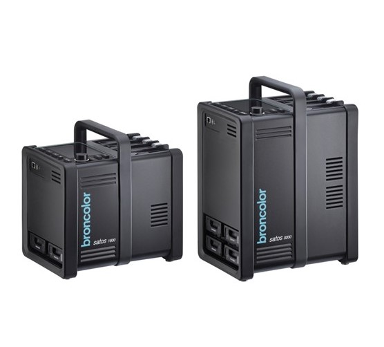 Satos
Satos
-
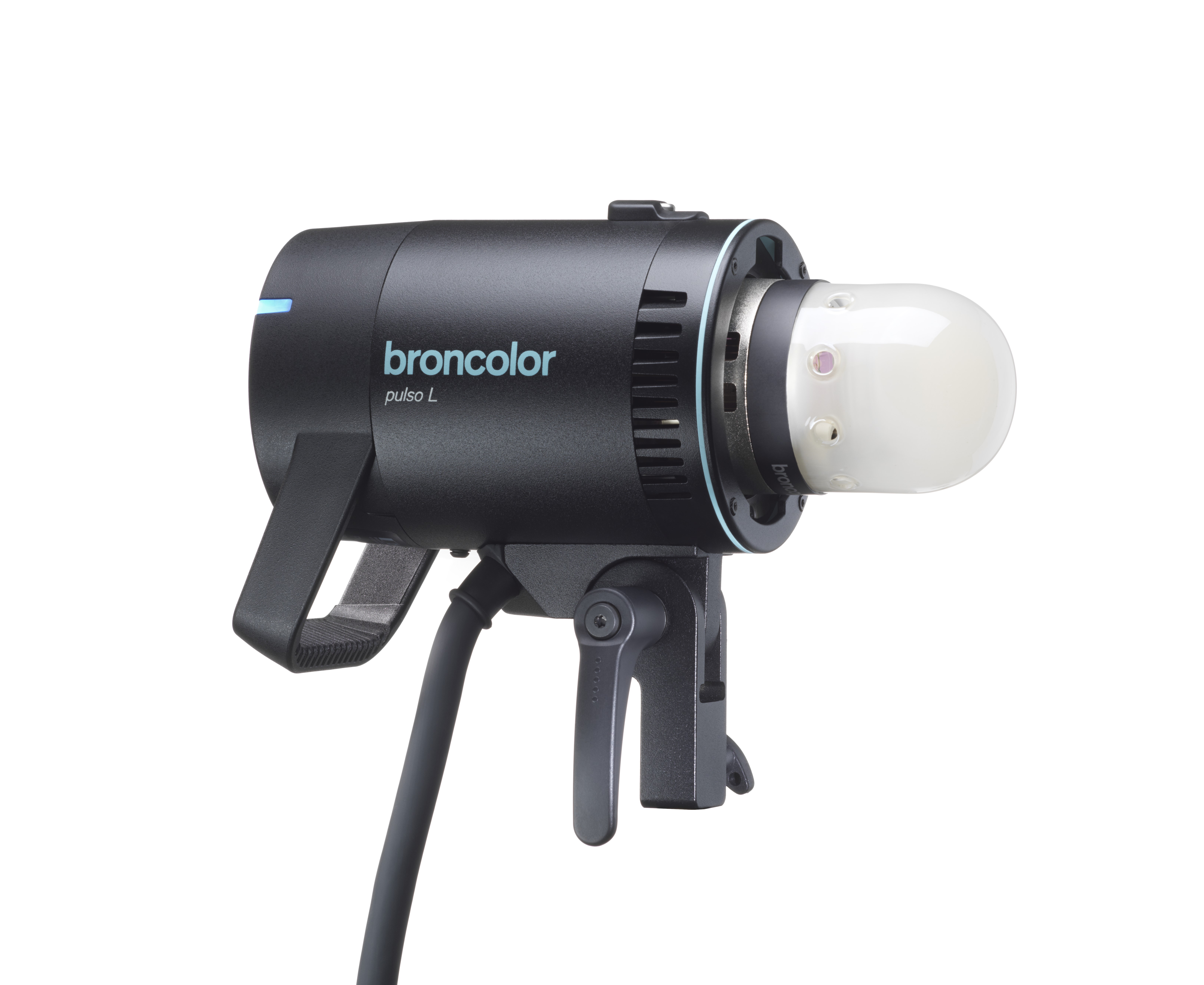 Pulso L
-
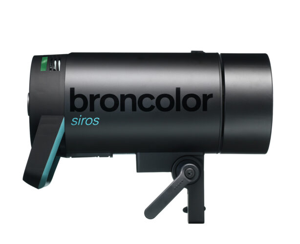 Siros S
-
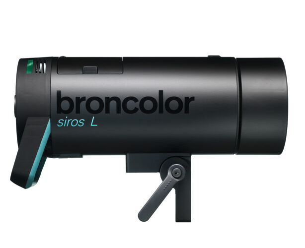 Siros L
-
 Scoro E + S
-
 Move 1200 L
-
 RFS 2.1
-
 RFS 2.2
-
 RFS 3
RFS 3
-
 Pulso G, Unilite and Picolite
-
 LED F160
-
 Scope D50
-
Compatibility (Lamp <-> light shaper | Lamp <-> power pack)
-
Locate your distributor or dealer
-
RFS 2 interface (Radio Frequency System)
Move power packs are supplied with RFS 2 installed as standard.
For RFS 2 flash control, the channel (studio address) must correspond to the transceiver’s RFS 2
channel. The channel (studio address) is defined in the LCD display under "studio address".
With the RFS 2 transceiver you can define and adjust the individual lamp connections on the flash
units as you wish. To make the adjustments, please follow the procedure given in the operating
instructions for the RFS 2 transceiver.
The RFS 2 transceiver is not included in the power pack’s scope of supply.
-
Photocell (cell)
The photocell can be switched on and off using the "sync" key. When it is active, the blue LED
beside the "cell" label is illuminated.
After the first flash of a sequence, the active photocell is deactivated, and the blue LED beside the
"sync" key blinks. Pressing the "sync" key switches on the photocell again.
-
Sync socket
The sync cables, 5 m (16.4 ft) (art. no. 34.111.00) and 10 m (32.8 ft) (34.112.00), can be fitted to the
sync socket for cable release.
-
"test" key
This key is used for manual release. A flash can be triggered as soon as 70 % of the set energy
level is reached. The visual ready indicator, on the other hand, only illuminates when 100 % is
attained.