Main menu functions overview (Satos)

-
Stelos 800 L
Stelos: Safety Instructions – read before use | Environment Stelos: Firmware update Stelos: User Interface | Controls | Functions | Handling Stelos: Technical Data Stelos: Remote control | Flash triggering Stelos: Power supply | Battery Stelos: Maintenance | Repair | Warranty Stelos: Accessories & Spare Parts Stelos: Error messages
-
Satos
Satos: Safety Instructions – read before use | Environment Satos: Firmware update Satos Satos: User Interface | Controls | Functions | Handling Satos: Technical Data Satos: Remote control | Flash triggering Satos: Power supply | Battery Satos: Maintenance | Repair | Consumables | Spare parts | Guarantee Satos: Accessories Satos: Charging station for up to 4 slide-in batteries
- Pulso L
-
Siros S
Siros S: Safety Instructions – read before use | Environment Siros S: Firmware update Siros S: User Interface | Controls | Functions | Handling Siros S: Technical Data Siros S: Remote control | Flash triggering Siros S: Power supply Siros S: Maintenance | Repair | Consumables | Spare parts | Guarantee Siros S: Accessories
-
Siros L
Siros L: Safety Instructions – read before use | Environment Siros L: Firmware update Siros L Siros L: User Interface | Controls | Functions | Handling Siros L: Technical Data Siros L: Remote control | Flash triggering Siros L: Power supply | Battery Siros L: Maintenance | Repair | Consumables | Spare parts | Guarantee Siros L: Accessories
- Scoro E + S
- Move 1200 L
- RFS 2.1
- RFS 2.2
-
RFS 3
RFS 3: Safety Instructions – read before use | Environment RFS 3: Scope of delivery and operating elements RFS 3: User Interface | Controls | Functions | Handling RFS 3: Firmware Update RFS 3.0 RFS 3: Compatibility RFS 3: Technical Data RFS 3: Maintenance | Repair | Consumables | Spare parts | Guarantee RFS 3: Trouble shooting
- Pulso G, Unilite and Picolite
- LED F160
- Scope D50
- Compatibility (Lamp <-> light shaper | Lamp <-> power pack)
- Locate your distributor or dealer
-
 Stelos 800 L
-
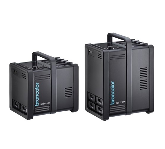 Satos
Satos
-
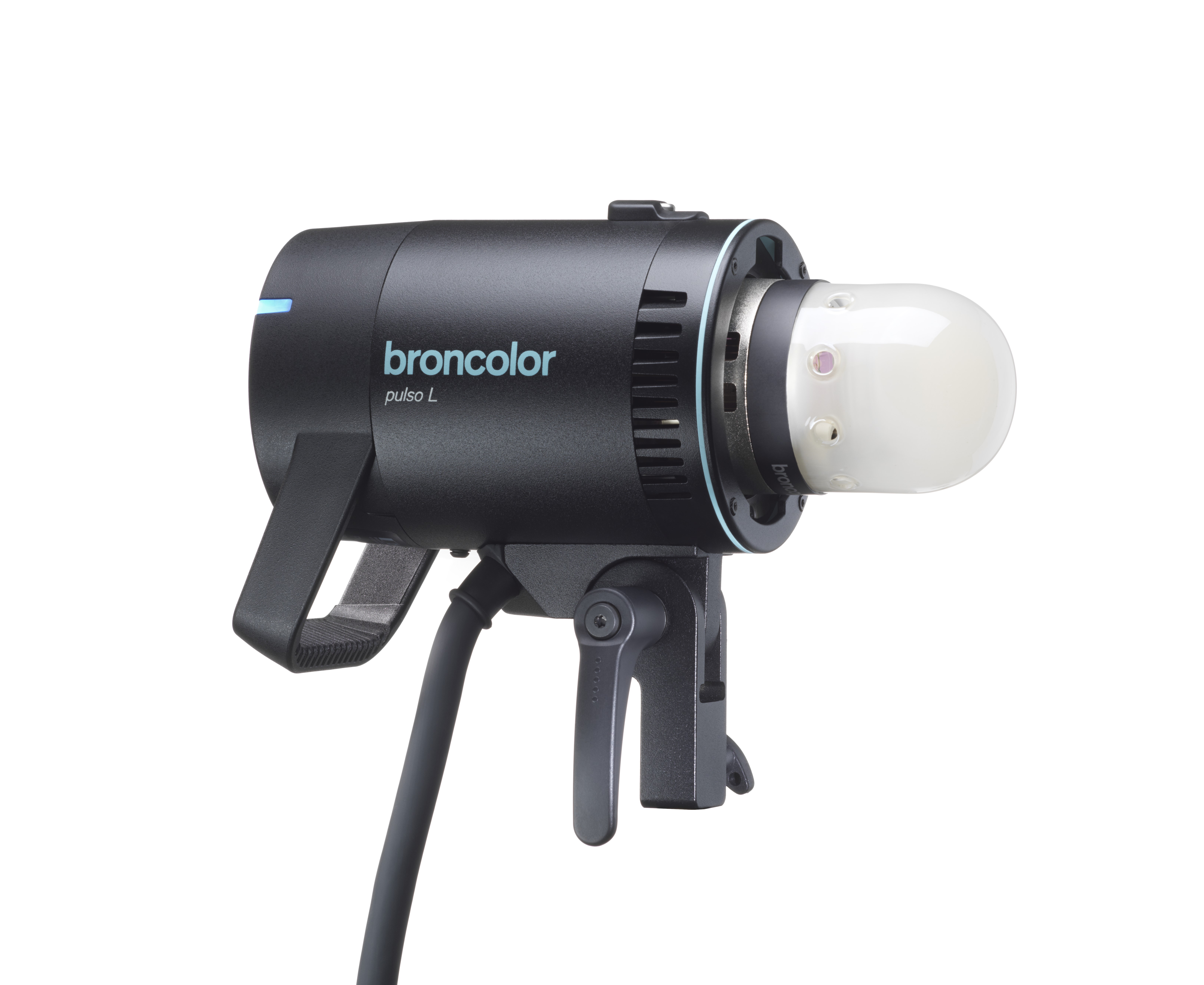 Pulso L
-
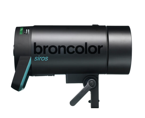 Siros S
-
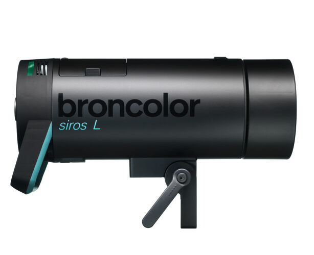 Siros L
-
 Scoro E + S
-
 Move 1200 L
-
 RFS 2.1
-
 RFS 2.2
-
 RFS 3
RFS 3
-
 Pulso G, Unilite and Picolite
-
 LED F160
-
 Scope D50
-
Compatibility (Lamp <-> light shaper | Lamp <-> power pack)
-
Locate your distributor or dealer
Main menu view
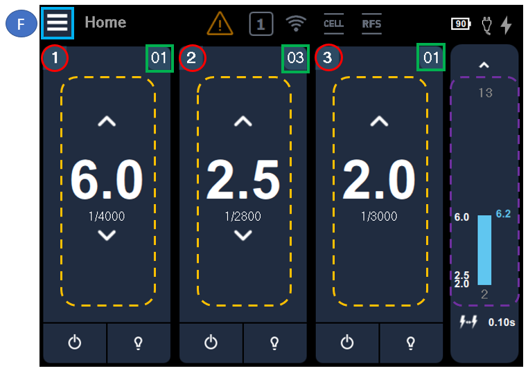
There are four visible "columns" representing the individual light channels (dashed yellow) 1, 2 and 3 as well as the "Master" (controls channels 1-3 simultaneously | dashed violet).
The focus (light blue border, "F") always remains on the position that you last activated with the push/turn control. Once you switch to finger control (touch), the focus is no longer visible. In the above example, the focus remains on the menu button in the upper left corner.
The red circles mark the respective number of the light channel. The display always indicates this and the values remain the same.
The green squares mark the respective light address. This display can be hidden under "More" in the submenu. The light address has significance when forming groups with radio remote control or when using the bronControl app. For example, if both light channels 1 and 3 are both set to "01", then it would be in the same group.
The central function of each channel is the power setting. The flash energy can be increased or reduced using the arrow buttons. A short push-button action changes the value in 0.1 intervals, a long push-button action increases the value in 1.0 intervals.
The master channel visualizes the accumulated power of channels 1 to 3 and demonstrates graphically how much control range remains available depending on the selected asymmetry:

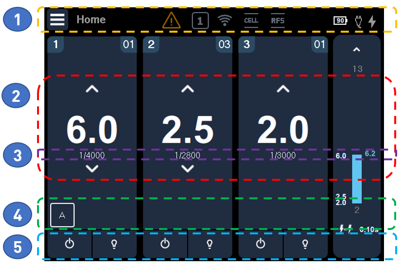
In principle, the main menu consists of five sections, as highlighted in color above.
1 - Info line (yellow section):
Being visible at all times, Satos informs you here about important, general functional conditions.
Click on the icon to open the respective function's menu.
|
Any malfunctions are indicated using this pictogram. If you can continue working, the icon turns orange. Red indicates that it is not possible to continue working. Please click on this icon to read the respective text message about the problem. Your broncolor partner has the expertise to provide you with further assistance in this regard, if required. |
|
The number displayed inside this icon represents the studio address that is currently adjusted. This number (channel) must be identical on your broncolor radio transmitter (RFS) and Satos unit for remote control via radio communication to work. |
|
This pictogram is displayed when there is at least one plug-in battery in the device. The percentage value displayed inside this icon indicates the average value of the current charging status of all the plug-in batteries located in the device. If the value drops below 20%, the icon turns orange and a warning tone beeps. |
|
This pictogram is displayed when there is at least one plug-in power supply unit in the device. |
|
If this pictogram is displayed, then it indicates that Satos is supplied with mains power and inserted rechargeable batteries can be recharged. |
|
|
This pictogram indicates that flash triggering using a photocell is activated. |
|
|
Triggering by radio pulse is activated. |
2 - Power (red area):
The flash energy can be set individually per channel or for all channels at the same time ("Master").
3 - Flash parameter (violet area):
The flash exposure time is displayed here. The "More" submenu can also be used to hide this.
4 - Special functions ("Timing" | green area):
A maximum of 3 special functions can be added per channel: "Alternate", "Delay" or "Sequence". The small square with "A" (Alternate) or the respective pictogram is displayed when the function is active. Click on the icon to open the special function menu directly. Detailed descriptions can be found in the respective chapter of these operating instructions.
|
|
Alternate |
|
|
Delay |
|
|
Sequence (sequence and associated interval) |
5 - (De)Activate light channels & modeling light (blue area):
Click on the icon ![]() to activate ("enable") or deactivate ("disable") a light channel temporarily.
to activate ("enable") or deactivate ("disable") a light channel temporarily.
Currently, all active parameters remain stored here.
All channels can be (de-)activated simultaneously with the physical Master push-button ![]() .
.
You can also control individual channels with the respective physical channel push-button.
The modeling light icon indicates whether the steady light is currently on or off:
|
|
Modeling light on |
|
|
Modeling light off |
In addition, the modelling light ![]() can also be controlled controlled with the physical "MOD" push-button.
can also be controlled controlled with the physical "MOD" push-button.
Short push-button action: The modeling light is switched on or off.
Long push-button action: The modeling light switches to "full" (maximum brightness). When the "mod" push-button is pressed shortly again, the modeling light switches back to the setting selected (in the submenu).
How to switch from the main menu ("Home") to the submenu?
Option 1:
Turn the rotary control to focus on the "Menu" icon ![]() in the upper left corner. Click on the turn control, and the submenu level will be displayed.
in the upper left corner. Click on the turn control, and the submenu level will be displayed.
Option 2:
Press the "Home | Menu" ![]() toggle push-button quickly.
toggle push-button quickly.